


THERMAL TIME LAPSE FOR CONSTRUCTION AND INDUSTRIAL PROCESSES
Temperature histories and visual documentation through synchronised thermal and RGB imaging
Sky Pictures Bulgaria offers project-specific thermal time-lapse solutions: repeated thermal-camera imaging that shows how the surface temperature of structures, assets and materials changes over time. Combined with RGB imagery, sensor records and a construction activity log, the method provides a traceable picture of processes that a single image cannot reveal.
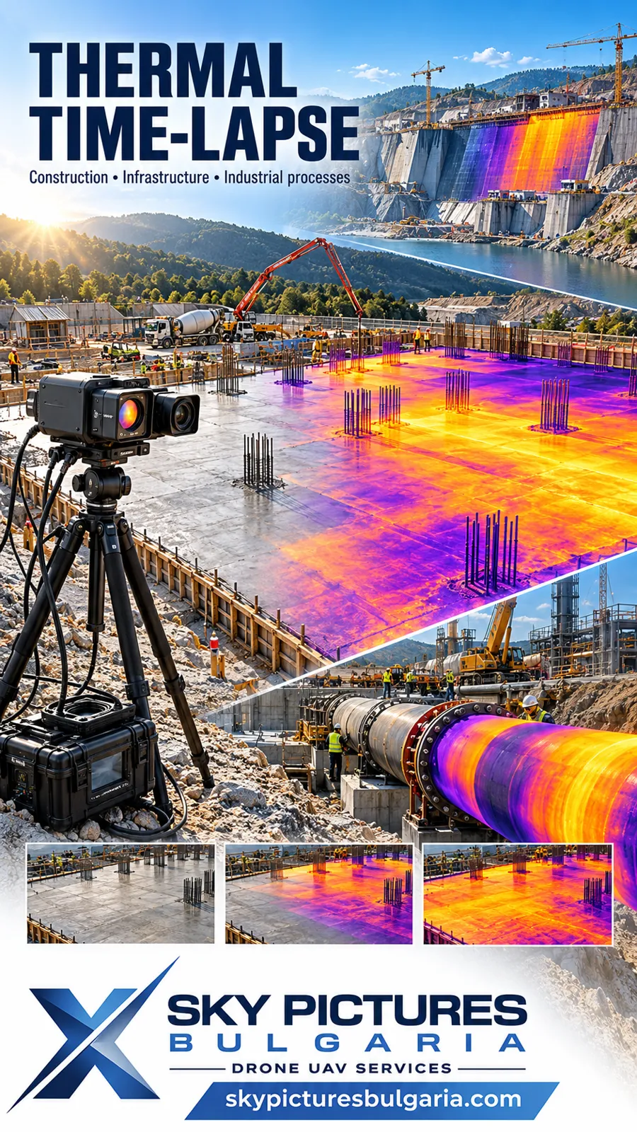
The service is intended for investors, construction companies, designers, construction supervisors, infrastructure operators and industrial businesses. Each configuration is designed around the engineering task, from observing concrete placement and subsequent cooling to tracking drying, heating, insulation work and equipment commissioning.
What Thermal Time Lapse Involves
A thermal camera records images at predefined intervals. Arranged chronologically, these can be presented as an accelerated video while also being retained as a measurement archive. Hours, days or longer project stages can be reviewed in a short sequence, with each image still linked to its actual capture time. [1]
With radiometric recording, a compatible original file retains measurement information for subsequent temperature analysis at selected points and regions. A colourised video or an ordinary screenshot alone is not equivalent to the radiometric data. [1, 2]
- Thermal imagery shows the distribution of surface temperatures and how it changes over time.
- RGB imagery records construction activities, visible surface conditions, equipment and the context of each event.
- Comparative analysis links a temperature change to a particular operation, area, stage or change in conditions.
Concrete and Heat of Hydration
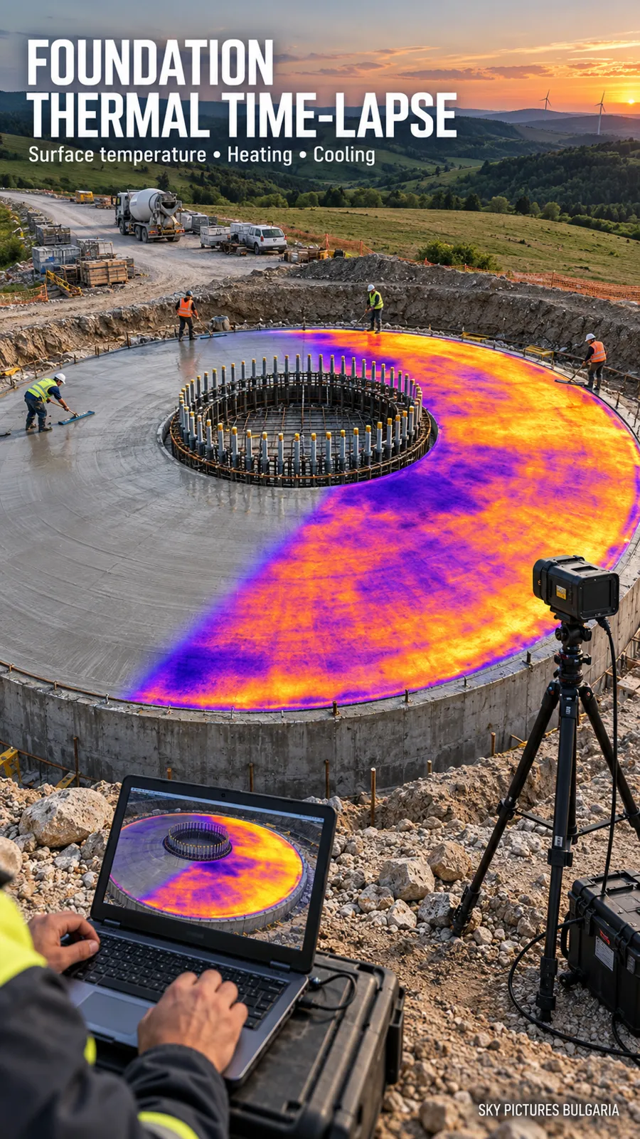
The hardening of cementitious materials involves chemical reactions that release heat. In large concrete elements, heat can accumulate internally while exposed surfaces cool more quickly. Depending on the mixture, geometry, environmental conditions and restraint of deformation, temperature differences can generate thermal stresses and a risk of cracking. [3, 4]
Thermal time lapse provides spatial and temporal information about surface heating and cooling. This helps the engineering team select areas for further checks and compare observations with the project's thermal control plan. The method does not directly measure the degree of hydration or concrete strength. [2–5]
What Can Be Tracked
- Surface temperature development after placement and differences in the behaviour of individual observed areas.
- Periods of more pronounced surface warming, heat retention and subsequent cooling.
- The behaviour of edges, corners, exposed surfaces and interfaces between construction stages.
- The visible temperature effect of covering, uncovering, changes to insulation, shading and other documented actions.
- The timing of thermal anomalies relative to weather changes and construction operations.
When Additional Sensors Are Required
A core-to-surface temperature difference requires measurements from appropriately positioned internal and surface sensors; a thermal camera cannot see through concrete. If the maturity method is used to estimate strength, it requires a time–temperature history and an established relationship for the particular concrete mixture. Formwork removal, loading and subsequent operations are decisions for the responsible specialists under the approved control programme. [2, 4, 5]
Main Applications
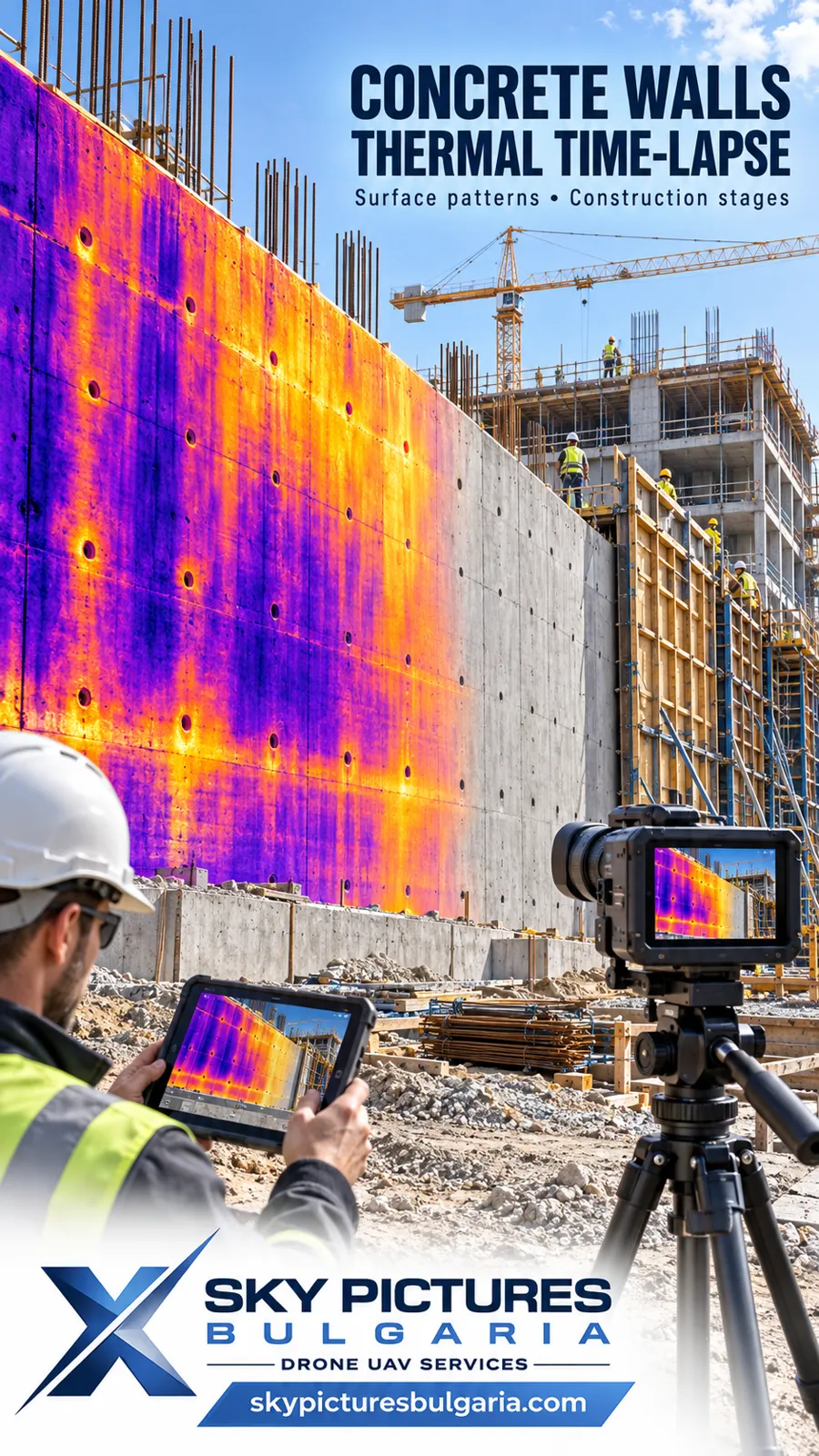
Foundations and Mass Concrete Structures
- Raft foundations, pile caps, foundation beams and foundations for heavy equipment.
- Wind turbine foundations, bridge piers, columns and substantial retaining walls.
- Comparison between separate pours and areas, accounting for differences in mixtures, geometry and weather.
Monitoring is planned around the critical stages identified by the engineering team. Where embedded sensors are installed, their records can be compared with the thermal and RGB sequences without treating the surface image as the temperature of the entire concrete volume.
Dams and Hydraulic Structures
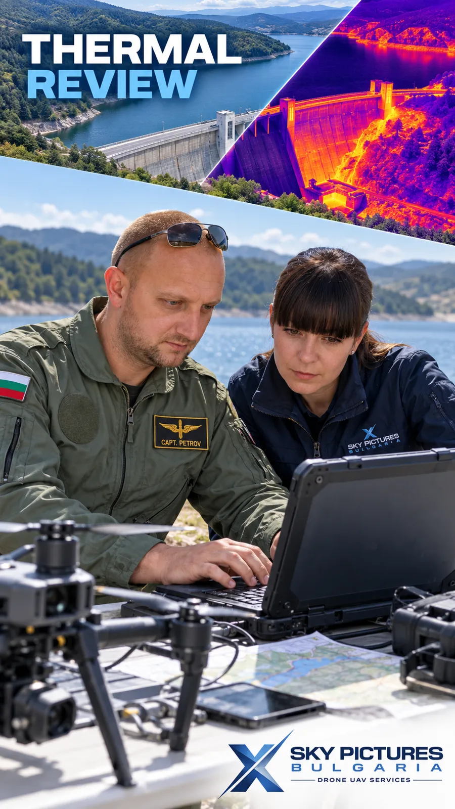
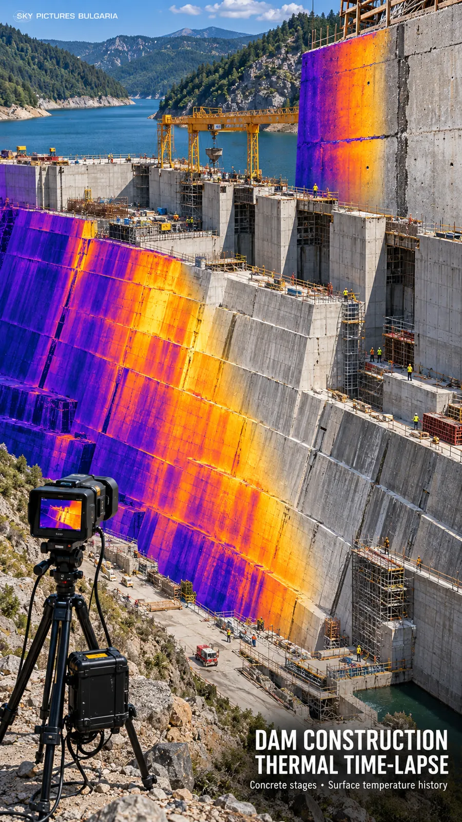
- Construction and repair of mass concrete blocks, intake towers, spillways and associated structures.
- Documentation of the temperature behaviour of accessible surfaces during individual construction stages.
- Observation of joints, interfaces and areas selected for additional engineering investigation.
On existing structures, temperature differences may indicate areas with different heat transfer or possible moisture. Confirming leakage, a defect or a watertightness problem requires additional investigation; thermography does not directly measure water flow through a structure. [6]
Buildings and Building Envelopes
- Façades, roofs, slabs and junctions during construction, refurbishment and repair.
- Comparison of thermal behaviour before and after insulation work under comparable conditions.
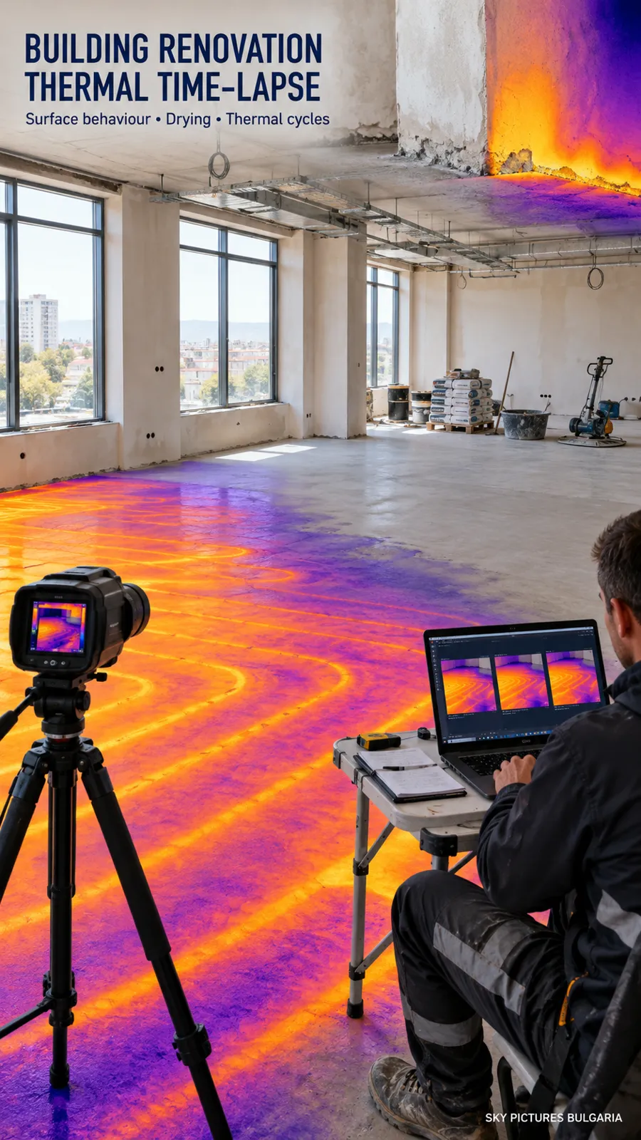
- Tracking temperature patterns associated with moisture and drying, with verification through suitable moisture measurements.
- Documentation of the visible effect of commissioning heating, underfloor heating and other thermal systems.
Roads Bridges and Pavements
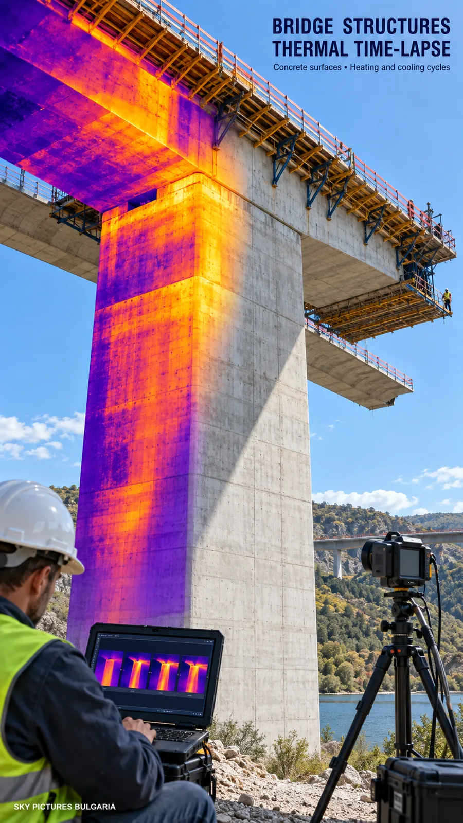
During asphalt work, thermal sequences can document cooling and temperature non-uniformity within the observed area. Continuous control along an entire paving route may require dedicated thermal profiling systems. The temperature image alone does not demonstrate achieved density or compaction quality. [7]
For concrete pavements and bridge elements, surface temperature cycles can be tracked. Under suitable thermal contrast, thermographic sequences can help identify suspect areas for delamination or other anomalies, which are then checked using additional methods. [7, 8]
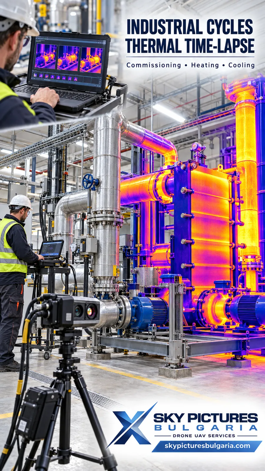
Industrial Processes and Commissioning
- Surface heating and cooling of equipment, pipework, tanks and insulation during trial operating conditions.
- Drying of coatings, screeds and repair materials where temperature behaviour is relevant to the process.
- Polymers and other materials with exothermic curing, following an assessment of suitability and the manufacturer's requirements.
- Comparison of visible temperature behaviour across successive operating cycles and after repair.
The scope is agreed with the process engineer or manufacturer. An observed surface temperature is not automatically treated as the temperature inside a material or machine.
Combining Thermal and RGB Imaging
Synchronised streams allow the same stage to be reviewed in both the thermal and visible spectra. Clocks are aligned, and image comparison accounts for differences in field of view, resolution and perspective.
- Side-by-side sequences show RGB and thermal images with a common timestamp.
- Split-screen and transitions show half the frame in RGB and half in thermal, or a gradual transition between the two.
- Transparent overlays follow spatial alignment, with the limitations of registration identified.
- Events and charts mark placement, covering, uncovering and other operations alongside temperature curves for selected regions.
A consistent colour scale is used within the comparison period, or changes to it are clearly identified. Automatic rescaling can make similar colours represent different temperatures and create a misleading impression.
How We Organise Monitoring
- Define the task – the structure, stages, observed surfaces, expected processes and questions the data needs to address.
- Agree the control programme – regions of interest, periods, sensors and review criteria defined with the designer, supervisor or process engineer.
- Inspect and configure – select cameras, lenses and positions; check visibility, access, power and equipment protection.
- Make a trial recording – verify focus, temperature range, time synchronisation, RGB quality and the radiometric archive.
- Capture and maintain traceability – scheduled recordings, an activity log, checks for missing data and retention of original files.
- Process and review – compare streams, produce charts and mark events; assess limitations and provide material for engineering interpretation.
- Deliver the results – the final time lapse, agreed data package, configuration details and a report suited to the project scope.
Technical Configuration and Duration
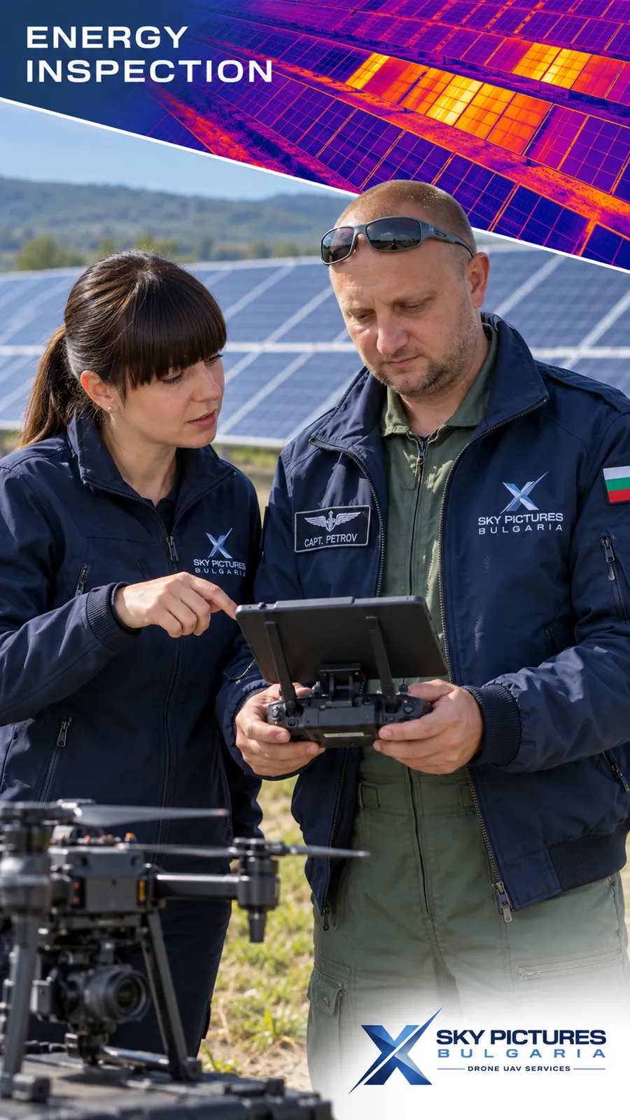
For extended monitoring, the principal solution is a stable fixed position on a tripod, structure or protected mount, without movement between frames. Multiple viewpoints can be planned where needed. A drone or mobile camera can provide supplementary periodic inspections; separate flights are not equivalent to uninterrupted recording from one fixed viewpoint.
- The duration can cover a specific operation, a day-and-night cycle, several days or a longer construction stage, depending on the technical arrangements.
- The interval is selected according to the speed of the process. Infrequent capture can miss a short temperature peak; rapid operations may require video or more frequent recordings.
- Power, backup provision, storage, protective housing and connectivity are planned for the site. Remote access and notifications are optional functions requiring compatible equipment and an available connection.
- A protective window must use material suitable for the camera's spectral band, with any necessary compensation; ordinary glass is not assumed to be transparent to a typical long-wave thermal camera. [9]
Measurement Reliability
Sound interpretation requires control of emissivity, reflected radiation, focus, distance, viewing angle and atmospheric effects. Sunlight, shadows, wind, rain, wet surfaces and changing finishes can alter the image independently of the process under investigation. [2, 8]
Formwork, thermal blankets and coverings obscure the concrete: the camera records their outside surface. Visibility and surface changes are documented when comparing stages. Quantitative tasks use appropriate reference measurements, with the camera's accuracy and the limitations of the particular setup stated. [10]
What the Client Receives
- A thermal time lapse with actual date and time, identification of the observed asset and an explanation of the colour scale.
- A synchronised RGB time lapse and/or a combined comparison video.
- Radiometric originals where that recording function was used, together with the agreed measurement archive.
- Temperature curves and exported tables for selected regions, such as minimum, maximum and mean surface temperatures and differences between observed areas.
- An event log identifying missing records, weather effects and limitations of comparison.
- A report describing observed anomalies and areas for further review; engineering conclusions and specialist testing are included only within an explicitly agreed scope involving competent specialists.
Important Interpretation Limits
Thermal time lapse does not guarantee detection of every crack and does not independently demonstrate structural safety. It can reveal temperature anomalies and process developments that guide further checks. Visible cracks are also documented using suitable RGB photography; their dimensions and causes are assessed through appropriate measurements and investigations.
There is no universal acceptable temperature or temperature difference for every asset. Criteria depend on the material, design, process and adopted requirements. The system supports the responsible specialists; it does not automatically change cooling, heating, watering or other process settings.
Benefits for the Project
- A process history allows the team to return to the moment a change occurred.
- Spatial context provides coverage of an accessible surface rather than only an individual measurement point.
- More targeted checks help select areas and periods that deserve additional attention.
- Better coordination gives the investor, contractor, designer and supervisor a shared visual record.
- Technical and presentation value combines measurement documentation with a clear account of project development.
Information Needed for a Proposal
Provide the location and description of the asset, dimensions and visible surfaces, material and process, work schedule, required duration, existing sensors, mounting and power arrangements, access requirements and desired deliverables. We also establish whether the objective is visual documentation, quantitative temperature analysis or integrated monitoring with the engineering team.
Sky Pictures Bulgaria develops a configuration for the specific task, from synchronised thermal and RGB sequences to a structured archive and comparative analysis. This allows the asset's development to be followed as both a visible construction process and a surface temperature history.
Video
OTHER SOLUTIONS
 01
AERIAL DRONE VIDEO SERVICES
Our team is fully certified for any work with unmanned aerial vehicles UAV/Drones…
VIEW MORE 02
VIDEO PRODUCTION SERVICES
Sky Picture Bulgaria provides quality video recording and filming in different video…
VIEW MORE 03
REMOTE MARKETING & INDUSTRIAL VIDEO PRODUCTION
Sky Pictures Bulgaria provides a modern remote production service for marketing,…
VIEW MORE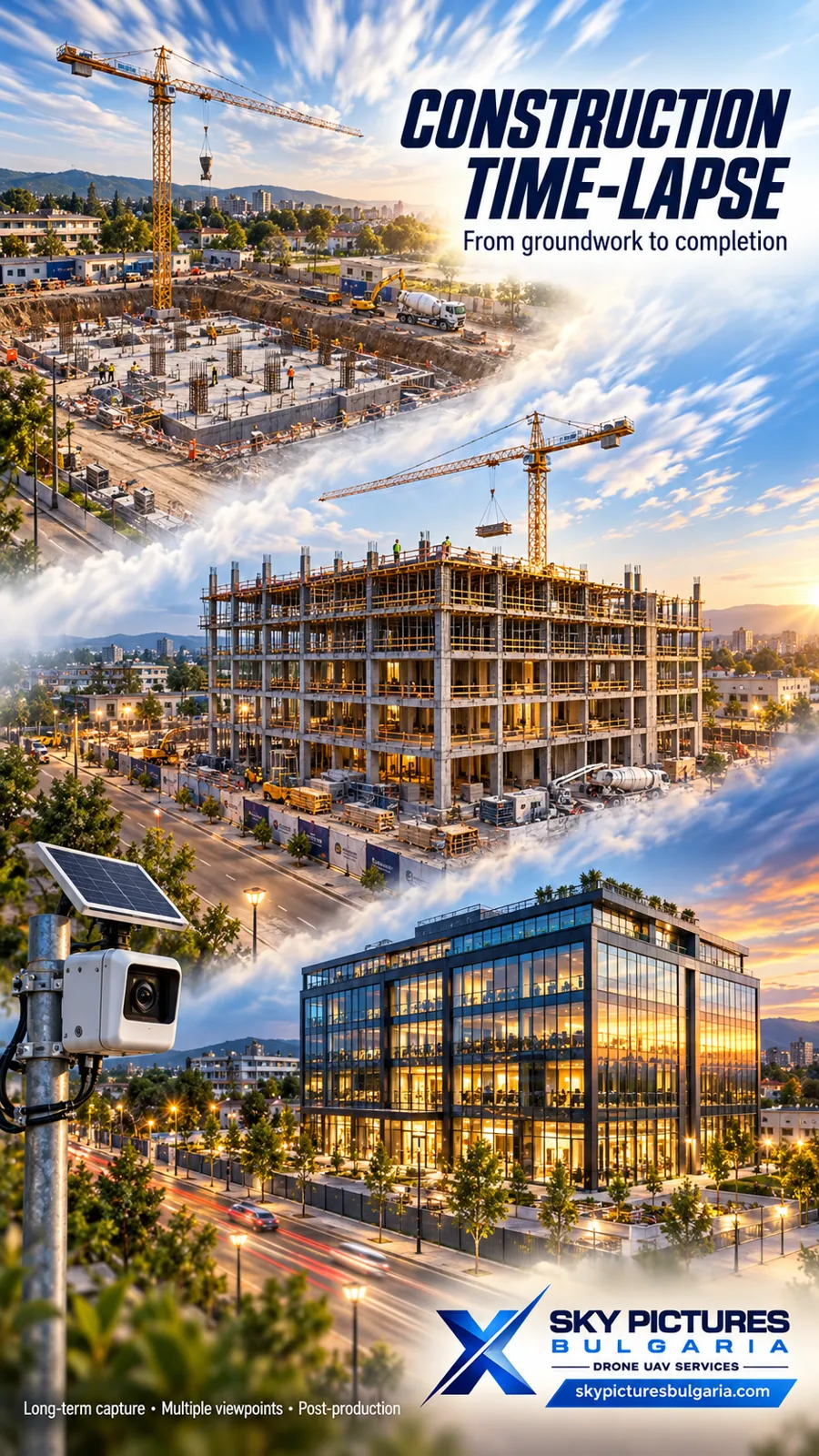 04
TIME LAPSE AND HYPERLAPSE VIDEO PRODUCTION SERVICES
Time-lapse and hyper-lapse filming give a unique and exceptional vision when filming…
VIEW MORE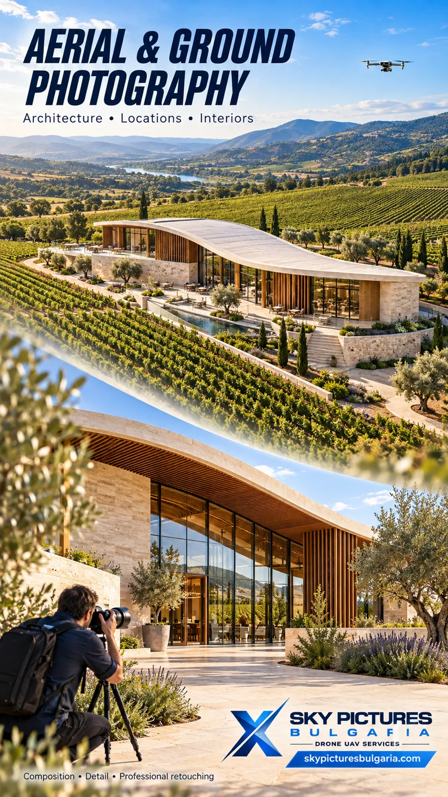 05
PHOTOGRAPHY
We offer complete solutions in the field of high-quality aerial and terrestrial…
VIEW MORE 06
FPV DRONE VIDEO SERVICES
VIEW MORE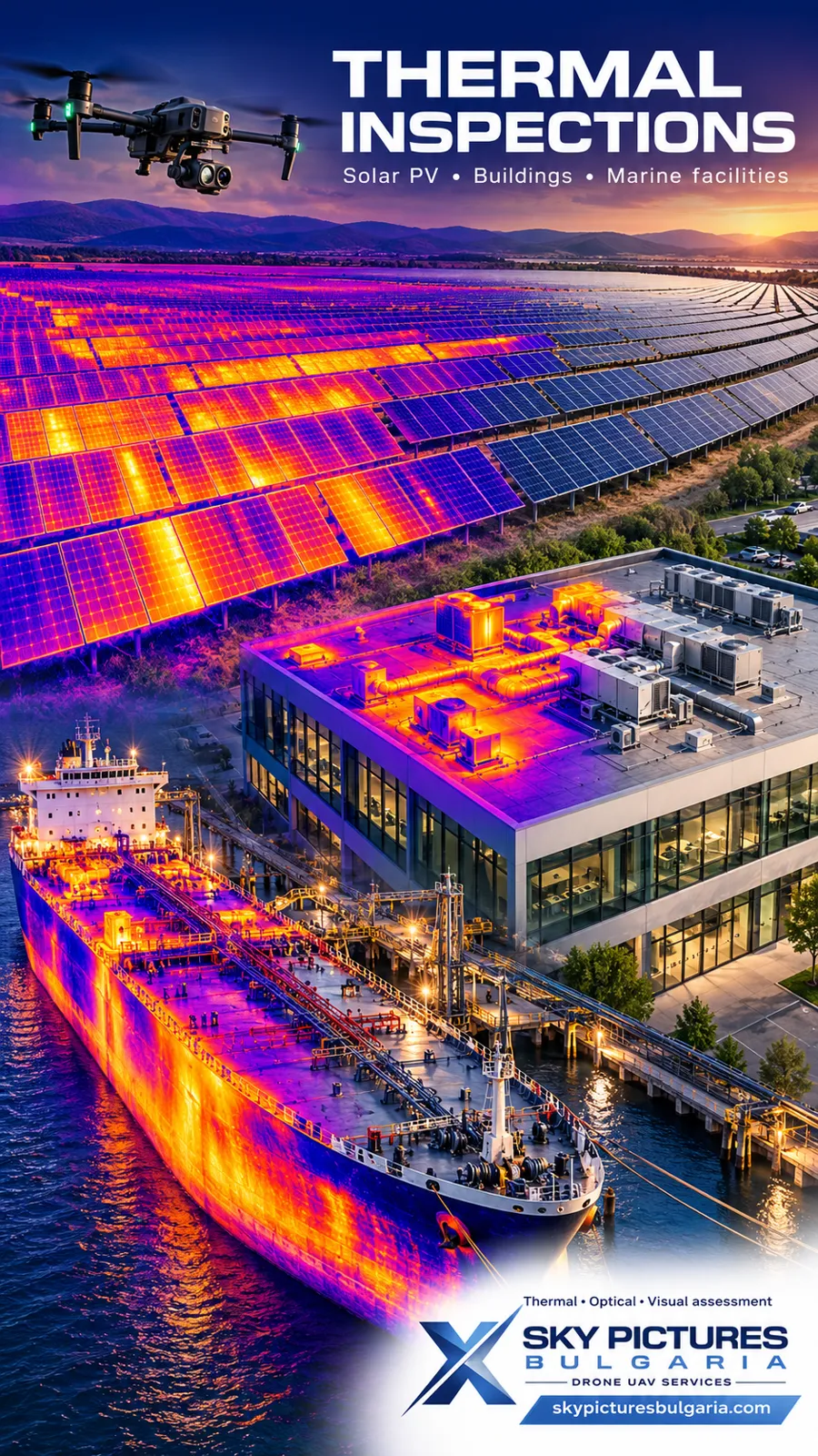 07
THERMAL DRONE INSPECTIONS
Petrov Sky Dynamics is a high-tech company owned by SKY PICTURES BULGARIA working mainly…
VIEW MORE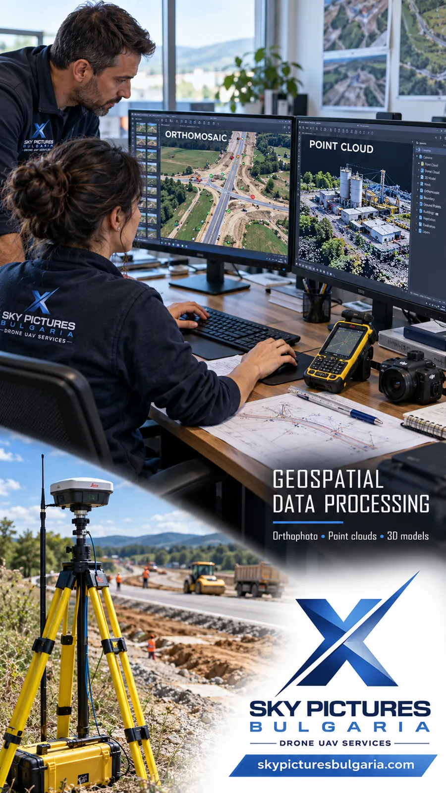 08
GEODETIC AND TOPOGRAPHIC SURVEYING WITH DRONES
VIEW MORE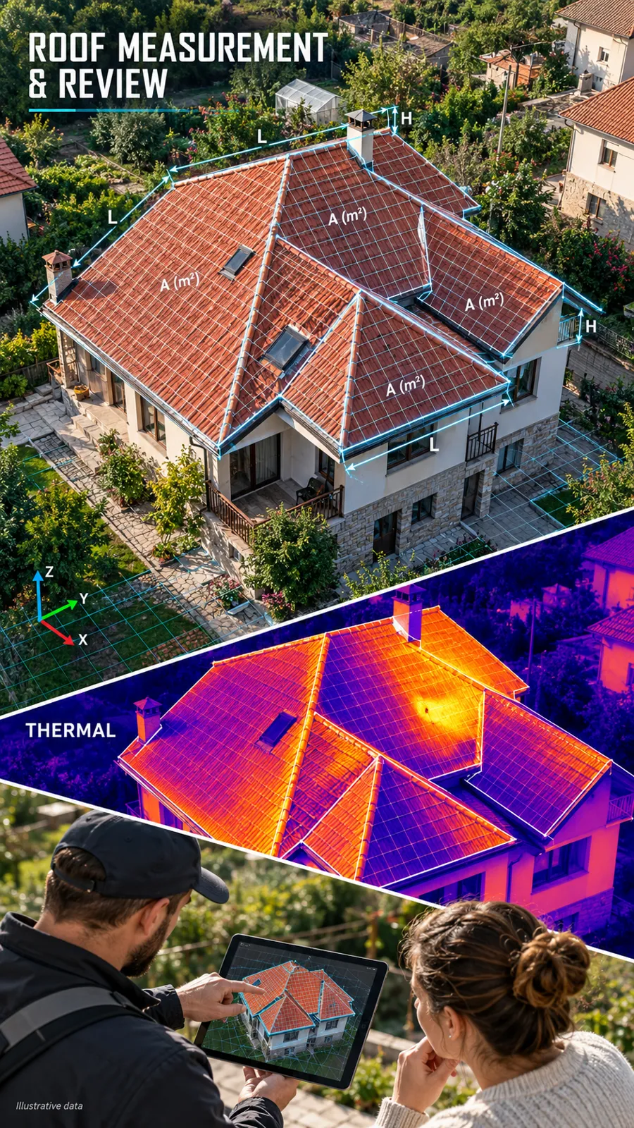 09
MEASUREMENT OF AREAS, VOLUMES, AND DISTANCES WITH INDUSTRIAL DRONES
VIEW MORE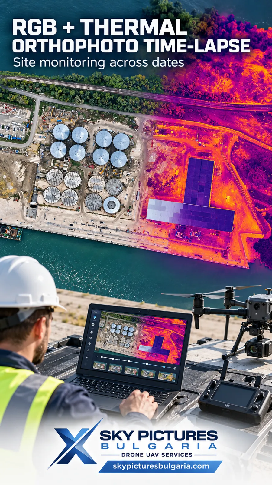 10
MONITORING CONSTRUCTION AND INDUSTRIAL SITES WITH RGB AND THERMAL ORTHOPHOTO TIME LAPSE
Comparison across dates, orthophoto time lapse and custom applications for measurement…
VIEW MORE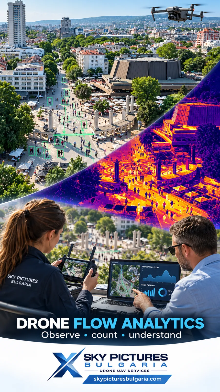 11
DRONE SYSTEMS FOR COLLECTING STATISTICAL DATA ON THE MOVEMENT OF PEOPLE
VIEW MORE 12
DRONE CONSULTING SERVICES
VIEW MORE 13
DRONE PILOT COURSES
VIEW MORE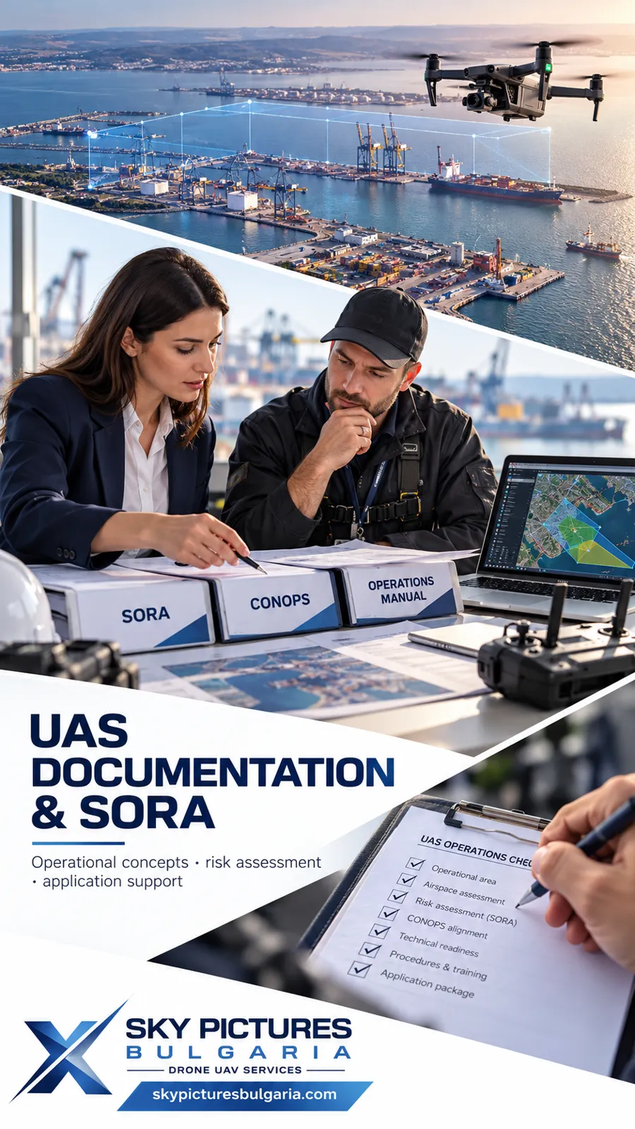 14
SPECIFIC CATEGORY DOCUMENTATION PREPARATION SORA REGULATORY AND OPERATIONAL DOCUMENTATION FOR UNMANNED AIRCRAFT SYSTEMS
Sky Pictures Bulgaria provides professional preparation, development, review and…
VIEW MORE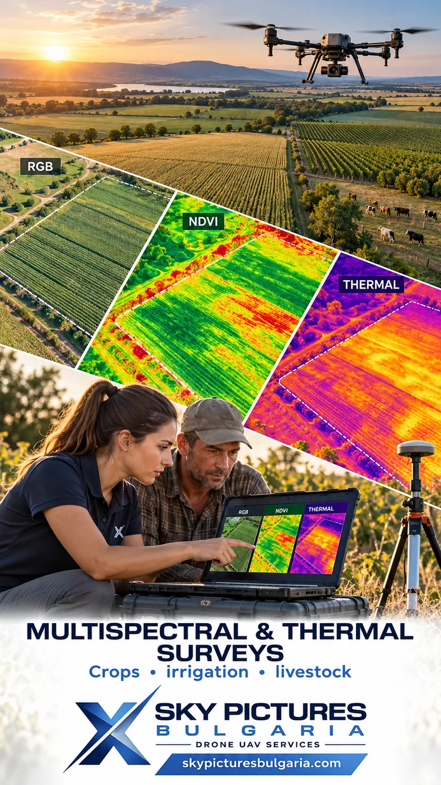 15
MULTISPECTRAL AND THERMAL DRONE SURVEYS FOR AGRICULTURE AND LIVESTOCK
VIEW MORE 16
AGRICULTURE DRONE SERVICES
VIEW MORE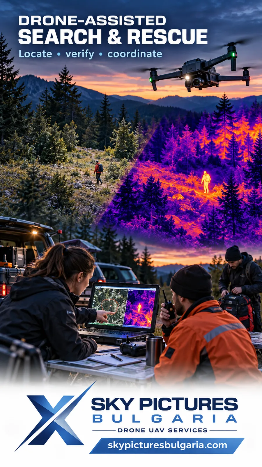 17
SEARCH AND RESCUE ASSISTANCE WITH THERMAL CAMERA DRONES
VIEW MORE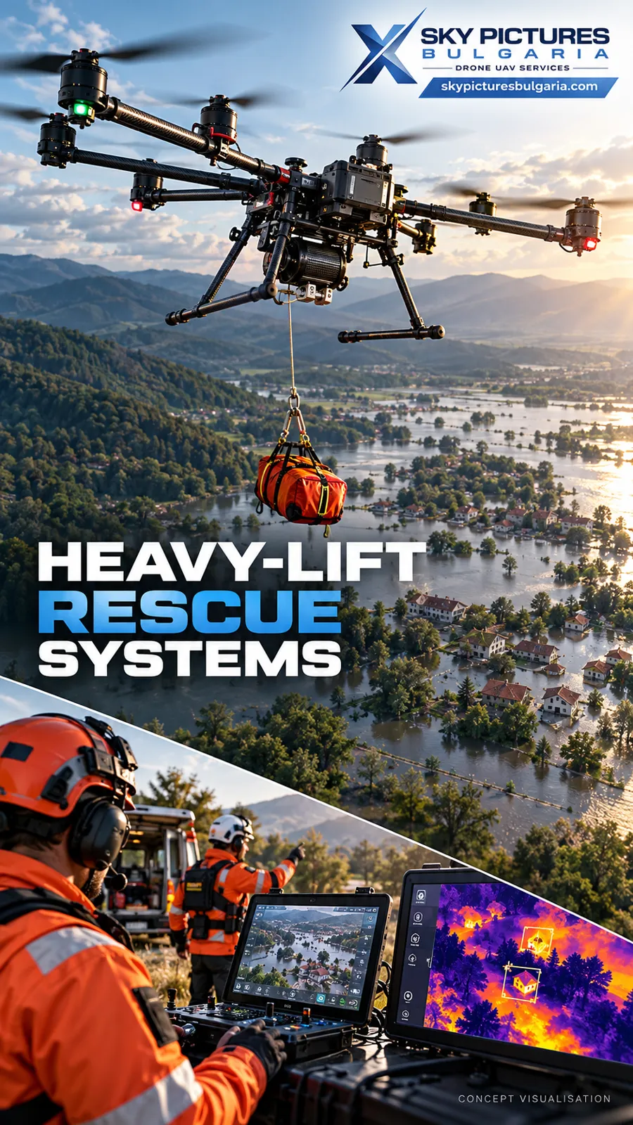 18
HEAVY-LIFT RESCUE DRONE SYSTEMS FOR HUMAN EVACUATION
Sky Pictures Bulgaria designs, develops and integrates heavy-lift unmanned aircraft…
VIEW MORE 19
SEARCH AND RESCUE OF PETS WITH THERMAL CAMERA DRONES
VIEW MORE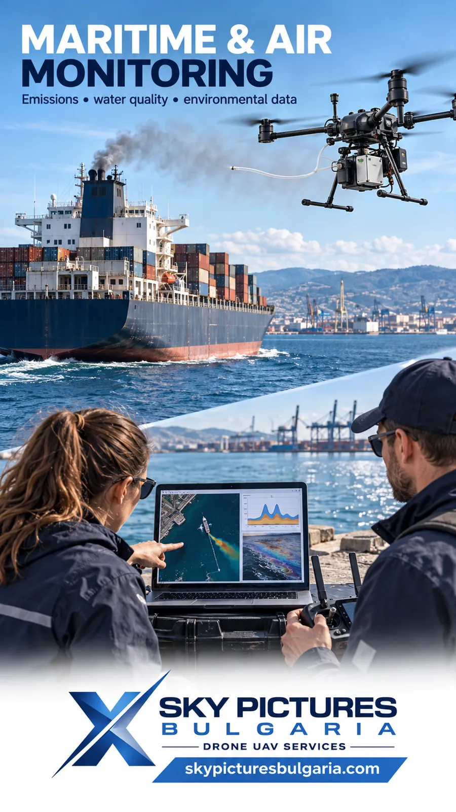 20
DRONE SYSTEMS FOR EXHAUST GAS ANALYSIS
VIEW MORE 21
DRONE ASSISTANCE FOR MARINE TRANSPORT UNDER LOW VISIBILITY CONDITIONS
VIEW MORE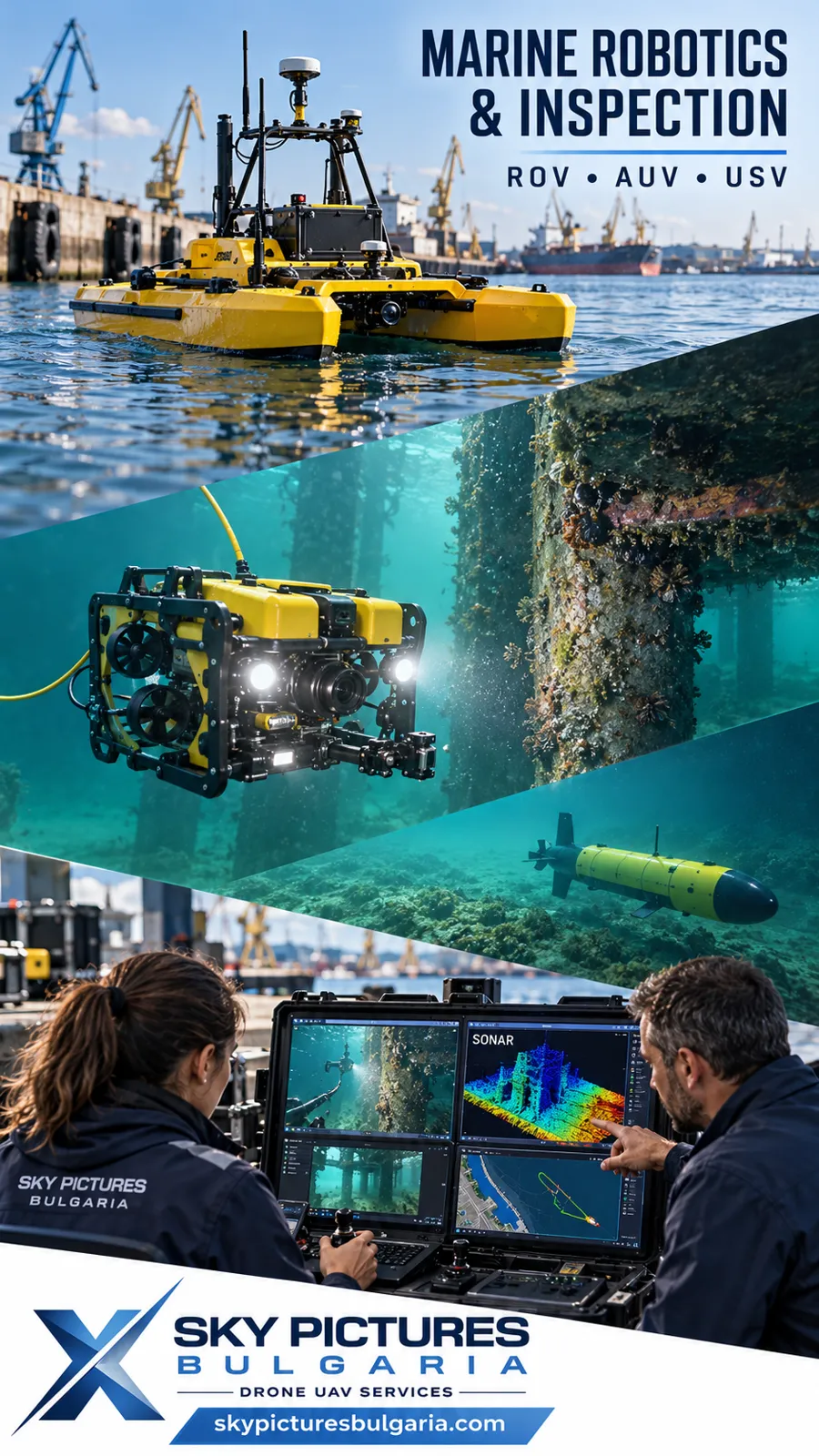 22
UNDERWATER SURFACE DRONE SYSTEMS FOR INSPECTIONS AND MONITORING ROV AUV USV
VIEW MORE 23
CARGO TRANSPORTATION WITH DRONES – FROM 1 GRAM TO 100 KG
VIEW MORE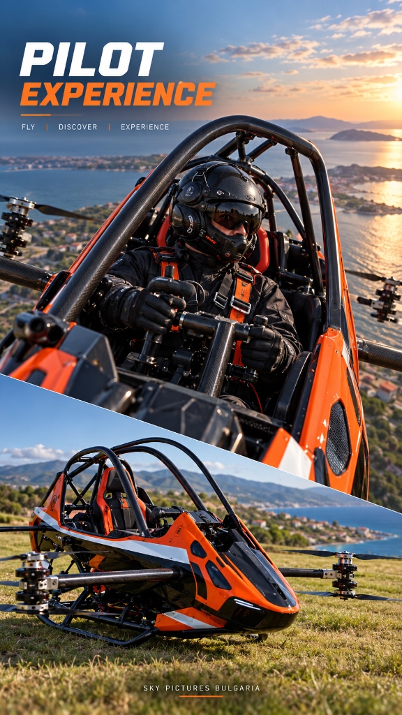 24
EVTOL INTELLIGENT ULTRA-LIGHT ELECTRIC AIRCRAFTS ANTG
ANTG-X6 is a single-seat, fully electric Vertical Take-Off and Landing (eVTOL) aircraft…
VIEW MORE 25
EVTOL VERTIPORTS INFRASTRUCTURE AND ADVANCED AIR MOBILITY
Sky Pictures Bulgaria plans, engineers and integrates end-to-end ecosystems for future…
VIEW MORE 26
SELL OF PROFESSIONAL DRONES
VIEW MORE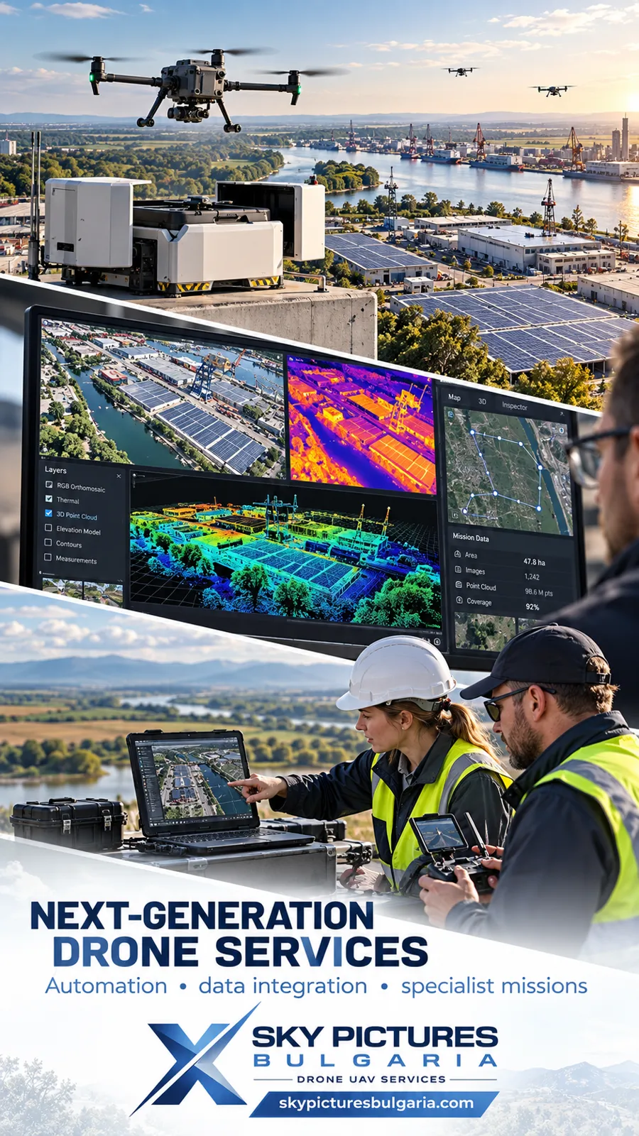 27
NEW INNOVATIVE AND HIGH-TECH DRONE SERVICES
VIEW MORE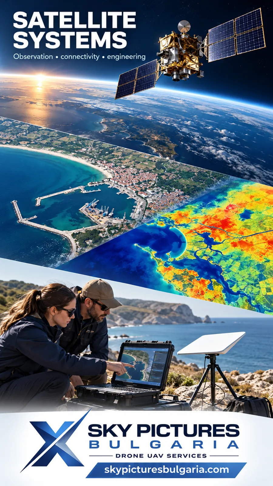 28
SATELLITE IMAGING, SATELLITE SYSTEM DESIGN, AND CONNECTIVITY FOR REMOTE AREAS SATELLITE INTERNET NETWORKS
VIEW MORE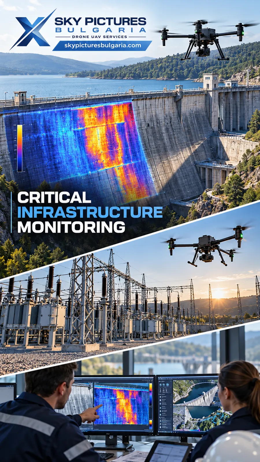 29
MONITORING AND PREDICTIVE INFRASTRUCTURE PLATFORMS
Next-Generation Solutions for Autonomous Monitoring, Digital Twins, Artificial…
VIEW MORE